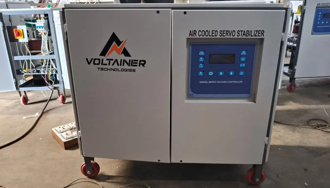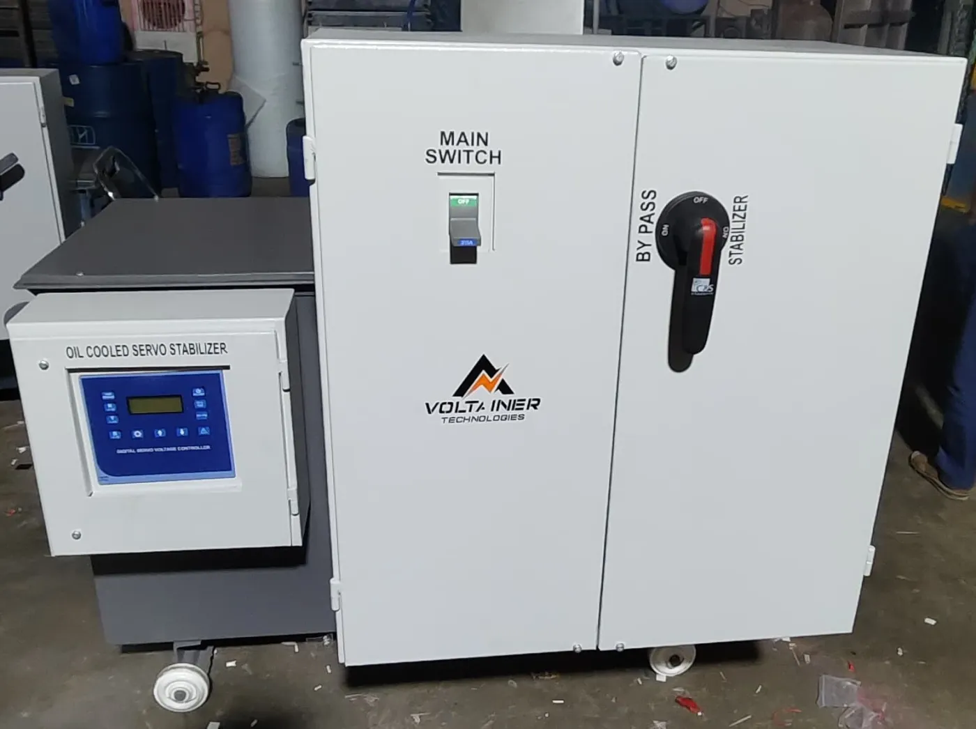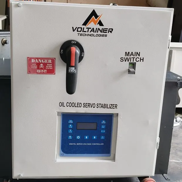
Servo stabilizers look simple from the outside, but inside they combine a precise control loop with robust magnetics. Here is how the main parts work together.
1. Sensing
The digital servo voltage controller measures the output voltage of each phase many times per second and compares it with the set value (for example 415 V).
2. Decision
If the output is outside the permitted band, the controller energises a servo motor in the required direction — up to raise voltage, down to lower it.
3. Correction
The servo motor rotates the carbon brush of a variac (a variable auto-transformer). The variac output feeds the primary of a buck-boost transformer, whose secondary is connected in series with the load. Depending on polarity, it adds to or subtracts from the incoming voltage.
4. Protection
If the input is outside the correctable range, or a fault such as overload, short circuit or single phasing occurs, the controller trips the output contactor to protect the load.
Because correction is continuous and the waveform passes through transformers rather than electronic switching, servo stabilizers introduce no waveform distortion and achieve efficiencies above 98%.